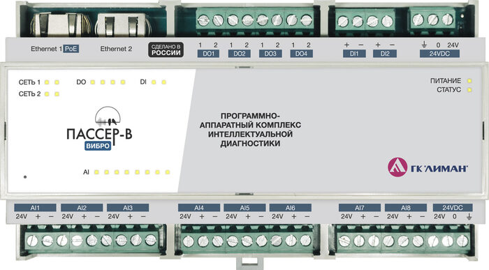
Passer-V
Passer-V is an industrial vibration signal acquisition controller for condition monitoring systems. Connects analog vibration sensors with 0–5 V output (ICP/IEPE accelerometers with external amplifier). Digitizes the raw signal at up to 92 kHz, computes RMS and crest factor, and transmits data to Larus, where spectral analysis (FFT) is performed.
| Parameter | Value |
|---|---|
| Part number | PSRV-220 |
| Device type | Vibration signal acquisition controller |
| Analog inputs | 8 × AI (0–5 V) |
| Discrete I/O | 2 × DI + 4 × DO |
| Sampling rate | up to 102.4 kHz |
| Power supply | 18–75 V DC (nom. 24 V) |
| Mounting | DIN rail 35 mm |
| Protection rating | IP20 |
| Status | 🟢 Active |
Key Features
- 8 analog inputs — connect up to 8 vibration sensors 0–5 V, accuracy ±0.3%
- Raw signal up to 92 kHz — transmits high-frequency signal to Larus for spectral analysis (FFT)
- Bandwidth up to 51.2 kHz — captures high-frequency defects (GMF, BPFI/BPFO)
- Synchronous acquisition — simultaneous measurement across all channels
- Discrete I/O — 2 DI for tachometers/alarms, 4 DO for protective shutdowns
- Automatic protection — configurable DO response to impact/collision without delay, suitable for emergency shutdown
- Industrial grade — −40 to +80 °C, 93% humidity non-condensing
- Shared form factor with Passer-T — interchangeable enclosure, DIN rail 35 mm
- Dual Ethernet ports — Ethernet 1 with PoE, Ethernet 2 for daisy-chaining
Technical Specifications
Analog Inputs (8 × AI)
| Parameter | Value |
|---|---|
| Number of channels | 8 (AI1–AI8) |
| Signal type | Analog, vibration |
| Voltage range | 0–5 V |
| Sampling rate | up to 102.4 kHz |
| Bandwidth | 0–51.2 kHz |
| Accuracy | ±0.3% (±3.0% in 10–50,000 Hz range) |
Digital Inputs (2 × DI)
| Parameter | Value |
|---|---|
| Number of channels | 2 (DI1–DI2) |
| Logic high voltage | 12–28 V |
| Pulse frequency range | 0–1 MHz |
| Minimum pulse duration | 1 μs |
Digital Outputs (4 × DO)
| Parameter | Value |
|---|---|
| Number of channels | 4 (DO1–DO4) |
| Switching voltage | 0–32 V |
| Switching current | 350 mA |
| On-state resistance | 1.6 Ω |
Power and Communication
| Parameter | Value |
|---|---|
| Supply voltage | 18–75 V DC (nominal 24 V) |
| Interface | Ethernet (2 × port, Ethernet 1 with PoE) |
| Protocol | Modbus TCP (port 502) |
| Default IP address | 192.168.0.100 |
Mechanical Specifications
| Parameter | Value |
|---|---|
| Dimensions (W × H × D), mm | 159.5 × 89.9 × 57.5 |
| Weight | max 0.4 kg |
| Mounting | DIN rail 35 mm |
| Enclosure material | ABS plastic UL94:V0 |
| Protection rating | IP20 |
Operating Conditions
| Parameter | Value |
|---|---|
| Operating temperature | −40…+80 °C |
| Relative humidity | 93%, non-condensing (at +40 °C) |
| Storage temperature | −50…+50 °C |
Reliability
| Parameter | Value |
|---|---|
| Average service life | 10 years |
| MTBF | 87,000 h |
Indicators
| Indicator | Color / state | Meaning |
|---|---|---|
| Status | Green | System powered and running |
| Yellow | Powering up, booting | |
| Red | Boot failure, fault | |
| Off | No power | |
| Power | Green | Voltage applied |
| Off | No input voltage | |
| Channel AI1–AI8 | Green | Channel active, sensor connected |
| Yellow | No sensor connected to channel | |
| Red | Channel not working | |
| DI 1–2 | Green | Channel active, signal present |
| Yellow | No signal connected | |
| Red | Channel not working | |
| DO 1–4 | Green | Closed state |
| Yellow | Open state | |
| Ethernet 1–2 | Green | Connection established |
| Off | No connection |
Variants
| Catalog number | Description | Features |
|---|---|---|
| PSRV-220 | Standard version | DIN rail 35 mm, IP20 |
Certificates and Compliance
| Certificate / declaration | Number | Authority / registry | Validity |
|---|---|---|---|
| TR CU 020/2011 Declaration (EMC) | — | — | — |
| TR CU 004/2011 Declaration (LVA) | — | — | — |
| CE | — | — | — |
| Russian Ministry of Industry registry | — | minpromtorg.gov.ru | indefinite |
Use Cases
- Bearing vibration monitoring — 0–5 V vibration sensors on bearing assemblies; raw signal is transmitted to Larus, where FFT detects BPFI/BPFO/BSF at an early stage; detection 7–14 days before failure.
- Gearbox and gear mesh diagnostics — high-frequency signal acquisition, GMF (gear mesh frequency) harmonic analysis performed on Larus.
- Test benches — 32 vibration points at 50 kHz, PTP (IEEE 1588) synchronization for multi-point measurements (example: UEC-Perm Engines).
- Mining industry — ball mill monitoring, 4–8 MW (example: Polyus Gold); prevention of unplanned shutdown costing >10M RUB.
Compatible Sensors
Passer-V supports the following sensor types:
Vibration accelerometers (inputs AI1–AI8):
| Model | Type |
|---|---|
| Ronds RH 103 | ICP/IEPE |
| TIK DVA 252.214.L5H1 | ICP/IEPE |
| Vibrotest A603C01 | ICP/IEPE |
| GTLab 1V265HN-100 | ICP/IEPE |
Tachometers (inputs DI1–DI2):
| Model | Type |
|---|---|
| LA30M-55.15P1.U1.K | Inductive (keyphasor) |
| VBO-M18-76V-5123-SA | Optical non-contact |
| Diffuse optical (type D) | For direct shaft access |
Preferred mounting method — rigid (stud/bolt on mounting pad). Magnetic mounting is acceptable only as a temporary measure. Approved adhesives: K300-61, Loctite EA3450 or equivalents.
Compatible Devices and Accessories
| Name | Type | Purpose |
|---|---|---|
| Larus-10 | IIoT gateway | Passer connection, data forwarding to LimanISU 2.0 |
| Larus-100 | Controller (PLC) | Passer connection + local control logic |
| Passer-T | Controller | Current diagnostics of the same machines (comprehensive picture) |
| Passer-Sch | Mounting board | Grounding monitoring in CVM100 enclosure |
| Vibration sensors 0–5 V | Sensors | ICP/IEPE accelerometers for input channels |
| LimanISU 2.0 | Software | Spectrum visualization, alerts, trend analysis |
Wiring Diagram
Vibration sensors                Passer-V
┌────────────────┐  0–5 V  ┌──────────────────────┐
│  Accelerometer │────────►│ AI1–AI8 (8 channels)  │
│  (0–5 V output)│         ├──────────────────────┤
└────────────────┘         │ DI1–DI2 (tachometers) │
┌────────────────┐         ├──────────────────────┤
│  Tachometer    │────────►│ DO1–DO4 (protection)  │
│  (DI, 12–28 V)│         ├──────────────────────┤    Modbus TCP
└────────────────┘         │ Ethernet 1 (PoE)      │──► Larus-10 / LimanISU
                           │ Ethernet 2             │
                           │ GND                    │
                           │ +18..75 V DC           │
                           └──────────────────────┘
Documentation and Downloads
| Document | Type | Date | Download |
|---|---|---|---|
| Technical specification (datasheet) | 26.12.2025 | ↓ download | |
| Technical specifications (TS) | 29.04.2025 | ↓ download | |
| Declaration of conformity | — | ↓ download | |
| Product passport | 07.08.2025 | ↓ download |
Software
| Software | Purpose |
|---|---|
| Embedded firmware | Loaded during manufacturing. Provides measurement, storage, and data transmission. Protected against unauthorized access |
| Corvus | GUI utility for debugging, calibration, and operating mode configuration via Modbus TCP |
| Modbus TCP module | Telemetry transmission to server (Larus-10 or LimanISU 2.0) |
Modbus TCP Register Map
Complete Modbus TCP register map for firmware v17+ (472 registers). Protocol: Modbus TCP, port 502.
System and Network (reg. 0–18)
| Register | Format | R/W | Description | Default | Notes |
|---|---|---|---|---|---|
| 0 | Int16 | R | CMD | — | 0x01 — save config; 0x02 — Goto BootLoader; 0x03 — Reboot |
| 1 | Int16 | R | Device type | 0x0002 | — |
| 2 | Int16 | R | Hardware version | 0x0002 | — |
| 3 | Int16 | R | Software version | 0x1010 | — |
| 4–5 | Int8×6 | R/W | Serial number | — | Writable only at default address |
| 6–8 | Int8×4 | R | MAC address | 0x0080E10000AA | — |
| 9–10 | Int8×4 | R/W | IP address | 192.168.0.100 | — |
| 11–12 | Int8×4 | R/W | Subnet mask | 255.255.255.0 | — |
| 13–14 | Int8×4 | R/W | Default gateway | 192.168.0.1 | — |
| 15–16 | Int8×4 | R/W | Server IP | 192.168.0.1 | — |
| 17 | Int16 | R/W | Modbus Slave ID | 1 | Range 1–250 |
| 18 | Int16 | R/W | Modbus TCP port | 502 | — |
Calibration (reg. 19–43)
| Register | Format | R/W | Description | Notes |
|---|---|---|---|---|
| 19 | Int16 | R/W | Channel for FFT analysis | 0–8 (channel number); >8 — FFT disabled |
| 20–27 | Int16 | R/W | Calibration coefficients AI1–AI8 | Signed ×1000 (e.g., 0.431 → 431) |
| 28–29 | Float32 | R/W | AI1 conversion coefficient (V → m/s²) | Formula: value = raw × calibr + addon |
| 30–31 | Float32 | R/W | AI2 conversion coefficient (V → m/s²) | — |
| 32–33 | Float32 | R/W | AI3 conversion coefficient (V → m/s²) | — |
| 34–35 | Float32 | R/W | AI4 conversion coefficient (V → m/s²) | — |
| 36–37 | Float32 | R/W | AI5 conversion coefficient (V → m/s²) | — |
| 38–39 | Float32 | R/W | AI6 conversion coefficient (V → m/s²) | — |
| 40–41 | Float32 | R/W | AI7 conversion coefficient (V → m/s²) | — |
| 42–43 | Float32 | R/W | AI8 conversion coefficient (V → m/s²) | — |
Channel AI1–AI8 Thresholds (reg. 44–314)
Each channel has 34 registers: Enable + 4 threshold groups (RMS / Amplitude / Peak-to-Peak / Crest Factor) × 3 levels (Notification / Warning / Alarm) + DO mask.
Channel AI1 (reg. 44–76):
| Register | Format | R/W | Description |
|---|---|---|---|
| 44 | Int16 | R/W | AI1 channel enable |
| 46–47 | Float32 | R/W | RMS — notification threshold |
| 48–49 | Float32 | R/W | RMS — warning threshold |
| 50–51 | Float32 | R/W | RMS — alarm threshold |
| 52 | Int16 | R/W | RMS — DO alarm mask |
| 54–55 | Float32 | R/W | Amplitude — notification threshold |
| 56–57 | Float32 | R/W | Amplitude — warning threshold |
| 58–59 | Float32 | R/W | Amplitude — alarm threshold |
| 60 | Int16 | R/W | Amplitude — DO alarm mask |
| 62–63 | Float32 | R/W | Peak-to-Peak — notification threshold |
| 64–65 | Float32 | R/W | Peak-to-Peak — warning threshold |
| 66–67 | Float32 | R/W | Peak-to-Peak — alarm threshold |
| 68 | Int16 | R/W | Peak-to-Peak — DO alarm mask |
| 70–71 | Float32 | R/W | Crest Factor — notification threshold |
| 72–73 | Float32 | R/W | Crest Factor — warning threshold |
| 74–75 | Float32 | R/W | Crest Factor — alarm threshold |
| 76 | Int16 | R/W | Crest Factor — DO alarm mask |
Channel AI2–AI8 offsets:
| Channel | Start | End | Offset from AI1 |
|---|---|---|---|
| AI2 | 78 | 110 | +34 |
| AI3 | 112 | 144 | +68 |
| AI4 | 146 | 178 | +102 |
| AI5 | 180 | 212 | +136 |
| AI6 | 214 | 246 | +170 |
| AI7 | 248 | 280 | +204 |
| AI8 | 282 | 314 | +238 |
Register structure for each channel is identical to AI1.
Current Values AI1–AI8 (reg. 316–379)
8 registers (4 × Float32) per channel — RMS, Amplitude, Peak-to-Peak, Crest Factor.
| Register | Format | Description |
|---|---|---|
| 316–317 | Float32 | AI1 — vibration acceleration RMS, m/s² |
| 318–319 | Float32 | AI1 — amplitude (peak value) |
| 320–321 | Float32 | AI1 — peak-to-peak |
| 322–323 | Float32 | AI1 — crest factor (amplitude / RMS) |
| 324–331 | Float32×4 | AI2 — RMS, amplitude, peak-to-peak, crest factor |
| 332–339 | Float32×4 | AI3 — RMS, amplitude, peak-to-peak, crest factor |
| 340–347 | Float32×4 | AI4 — RMS, amplitude, peak-to-peak, crest factor |
| 348–355 | Float32×4 | AI5 — RMS, amplitude, peak-to-peak, crest factor |
| 356–363 | Float32×4 | AI6 — RMS, amplitude, peak-to-peak, crest factor |
| 364–371 | Float32×4 | AI7 — RMS, amplitude, peak-to-peak, crest factor |
| 372–379 | Float32×4 | AI8 — RMS, amplitude, peak-to-peak, crest factor |
Threshold Status (reg. 380–411)
| Register | Format | Description |
|---|---|---|
| 380 | WORD | AI1 threshold status |
| 381 | WORD | AI2 threshold status |
| … | … | … |
| 387 | WORD | AI8 threshold status |
| 388–411 | — | Reserved |
Status bits: bit0 = RMS, bit1 = Amplitude, bit2 = Peak-to-Peak, bit3 = Crest Factor.
Values: STATE_NORMA=1, STATE_NOTIFIC=2, STATE_WARNING=4, STATE_ALARM=8 (OR logic).
FFT and Vibration Velocity (reg. 412, 440–455)
| Register | Format | R/W | Description |
|---|---|---|---|
| 412 | Int16 | R | FFT channel frequency, Hz |
| 440–441 | Float32 | R | AI1 vibration velocity, mm/s |
| 442–443 | Float32 | R | AI2 vibration velocity, mm/s |
| 444–445 | Float32 | R | AI3 vibration velocity, mm/s |
| 446–447 | Float32 | R | AI4 vibration velocity, mm/s |
| 448–449 | Float32 | R | AI5 vibration velocity, mm/s |
| 450–451 | Float32 | R | AI6 vibration velocity, mm/s |
| 452–453 | Float32 | R | AI7 vibration velocity, mm/s |
| 454–455 | Float32 | R | AI8 vibration velocity, mm/s |
Digital Outputs DO1–DO4 (reg. 413–420)
| Register | Format | Description |
|---|---|---|
| 413 | Int16 | DO1 — current value (0/1) |
| 414 | Int16 | DO1 — alarm trigger mask |
| 415 | Int16 | DO2 — current value (0/1) |
| 416 | Int16 | DO2 — alarm trigger mask |
| 417 | Int16 | DO3 — current value (0/1) |
| 418 | Int16 | DO3 — alarm trigger mask |
| 419 | Int16 | DO4 — current value (0/1) |
| 420 | Int16 | DO4 — alarm trigger mask |
Digital Inputs DI1–DI2 (reg. 422–433)
| Register | Format | Description |
|---|---|---|
| 422 | Int16 | DI1 — enable processing |
| 423 | Int16 | DI1 — instantaneous value (0/1) |
| 424–425 | Int32 | DI1 — pulse frequency (÷10), Hz |
| 426–427 | Int32 | DI1 — pulse period, ms |
| 428 | Int16 | DI2 — enable processing |
| 429 | Int16 | DI2 — instantaneous value (0/1) |
| 430–431 | Int32 | DI2 — pulse frequency (÷10), Hz |
| 432–433 | Int32 | DI2 — pulse period, ms |
Reset timers: frequency resets after 7 s without pulses, period — after 5 min. Filter: moving average of 24 values (since v16+).
Raw Signal Recording (reg. 434–438)
| Register | Format | Description |
|---|---|---|
| 434–435 | Int32 | Record command — start timestamp (0 — stop in cyclic mode) |
| 436 | Int16 | Recording mode: 0 — single 2 s; 1 — cyclic; 0x8000 — test sawtooth |
| 437 | Int16 | ADC frequency divider (1–14). Optimal for Passer-V: 1 |
| 438 | Int16 | Raw signal send timer, sec (min. 10; 0 = disabled) |
Sampling rates (reg. 437, FreqDiv):
| FreqDiv | Frequency, Hz |
|---|---|
| 1 | 92,778 |
| 2 | 54,575 |
| 3 | 37,111 |
| 4 | 28,114 |
| 5 | 22,628 |
| 6 | 18,934 |
| 7 | 16,277 |
| 8 | 14,273 |
| 9 | 12,709 |
| 10 | 11,454 |
| 11 | 10,424 |
| 12 | 9,565 |
| 13 | 8,836 |
| 14 | 8,210 |
Fixed Addons (reg. 456–471)
Added in v17. Additive correction to input signal: value = raw × calibr + fix_addon.
| Register | Format | R/W | Description |
|---|---|---|---|
| 456–457 | Float32 | R/W | Fixed addon AI1 |
| 458–459 | Float32 | R/W | Fixed addon AI2 |
| 460–461 | Float32 | R/W | Fixed addon AI3 |
| 462–463 | Float32 | R/W | Fixed addon AI4 |
| 464–465 | Float32 | R/W | Fixed addon AI5 |
| 466–467 | Float32 | R/W | Fixed addon AI6 |
| 468–469 | Float32 | R/W | Fixed addon AI7 |
| 470–471 | Float32 | R/W | Fixed addon AI8 |
Default: 0. Accepts positive and negative values.
Maintenance
| Maintenance type | Frequency | Activities |
|---|---|---|
| Visual inspection | Once per shift | Check indicators (power, AI, DI/DO, Ethernet), enclosure inspection |
| Weekly maintenance | Once per week | Check cables, sensor shielding, grounding |
| Monthly maintenance | Once per month | Diagnose all channels, check Modbus registers, clean dust |
| Quarterly maintenance | Once per 3 months | Comprehensive check, cable insulation (megger), heat monitoring |
| Unscheduled maintenance | As needed | After mechanical impacts, faults, or extended downtime |
Firmware
| Version | File | Date | What's new |
|---|---|---|---|
| v22 | pv22.bin | 12.2025 | RawData uint16 format, 650K sample buffer (~7 s at 100 kHz), auto-record on alarm, send limit once per 20 s |
| v21 | — | 2025 | Complete rewrite of raw signal buffers and TFTP, removed DMA copying |
| v20 | — | 2025 | Test sawtooth mode (RawRecordMode 0x8000), fixed buffer order (timestamps) |
| v17 | — | 2025 | FixAddon registers (456–471), new ring buffer format for raw signal |
| v16 | — | 2025 | DI moving average filter order increased from 4 to 24 |
| v14 | — | 2025 | 15 sampling rates (8.2–92.8 kHz), extended DI range |
| v13 | — | 2025 | Alarm register recording in RawData, alarm flags with OR logic |
| v9 | — | 2025 | Added vibration velocity (8 registers, 440–455) |
| v7 | — | 2025 | Raw signal send timer (reg. 438) |
| v4 | — | 2025 | 103 kHz sampling rate, DO emergency protection |
Bootloader: passerboot4.bin (current).
Float32 RawData variant of v22: pv22_float.bin.
Lifecycle and Support
Status: 🟢 Active (production and support) Planned EOL: not announced
Technical support:
Passer-V is for vibration monitoring. For electric motor diagnostics without mechanical intervention, choose Passer-T.