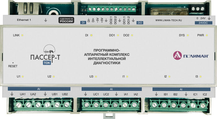
Passer-T
Passer-T is an industrial controller for monitoring and diagnostics of three-phase electric drives (pumps, fans, compressors). Simultaneously measures voltages (0–400 V) and currents (0–5 A) across all three phases. Performs Motor Current Signature Analysis (MCSA) to detect motor defects without mechanical intervention.
| Parameter | Value |
|---|---|
| Part number | PSRT-110 |
| Device type | Current and voltage measurement controller |
| Current channels | 3 × I (0–5 A) |
| Voltage channels | 3 × U (0–400 V) |
| Discrete I/O | 2 × DI + 4 × DO |
| Sampling rate | up to 103 kHz |
| Power supply | 18–75 V DC (nom. 24 V) |
| Mounting | DIN rail 35 mm |
| Protection rating | IP20 |
| Status | 🟢 Active |
Key Features
- Three-phase measurement — simultaneous monitoring of 3 voltage phases (0–400 V) and current phases (0–5 A)
- MCSA diagnostics — Motor Current Signature Analysis for detecting rotor, stator, and bearing defects
- Non-stop installation — current transformer snaps onto cable in 15 minutes without cutting
- Explosion-safe mounting — CT is installed outside the explosion-proof barrier
- Discrete I/O — DI for signaling, DO for protective shutdowns
- Industrial grade — −25 to +80 °C, 93% humidity non-condensing
- Shared form factor with Passer-V — interchangeable enclosure, DIN rail 35 mm
Technical Specifications
Voltage Measurement Channels (3 × U)
| Parameter | Value |
|---|---|
| Number of channels | 3 (U1–U3, phases A/B/C) |
| Voltage range | 0–400 V |
| Connection | Terminal block X3 |
| Cable | 0.75–1.5 mm², length up to 30 m |
Current Measurement Channels (3 × I)
| Parameter | Value |
|---|---|
| Number of channels | 3 (I1–I3, phases A/B/C) |
| Nominal input current | 5 A |
| Connection | Terminal block X4 via CT |
| Sampling rate | up to 103 kHz |
When disconnecting measurement circuits, CT secondary windings must be short-circuited.
Digital Inputs (2 × DI)
| Parameter | Value |
|---|---|
| Number of channels | 2 (DI1–DI2) |
| Logic high voltage | 12–28 V |
| Purpose | Tachometers (speed measurement) |
Digital Outputs (4 × DO)
| Parameter | Value |
|---|---|
| Number of channels | 4 (DO1–DO4) |
| Switching voltage | 0–32 V |
| Switching current | 100 mA |
| On-state resistance | 2 Ω |
Power and Communication
| Parameter | Value |
|---|---|
| Supply voltage | 18–75 V DC (nominal 24 V) |
| Interface | Ethernet (2 × port, Ethernet 1 with PoE) |
| Protocol | Modbus TCP (port 502) |
| Default IP address | 192.168.0.100 |
Mechanical Specifications
| Parameter | Value |
|---|---|
| Dimensions (W × H × D), mm | 159.5 × 89.9 × 57.5 |
| Weight | max 0.4 kg |
| Mounting | DIN rail 35 mm |
| Enclosure material | ABS plastic UL94:V0 |
| Protection rating | IP20 |
Operating Conditions
| Parameter | Value |
|---|---|
| Operating temperature | −25…+50 °C |
| Relative humidity | 93%, non-condensing (at +40 °C) |
| Storage temperature | −50…+50 °C |
Indicators
| Indicator | Color / state | Meaning |
|---|---|---|
| Status | Green | System powered and running |
| Yellow | Powering up, booting | |
| Red | Boot failure, fault | |
| Off | No power | |
| Power | Green | Voltage applied |
| Off | No input voltage | |
| AI channels | Green | Channel active, sensor connected |
| Yellow | No sensor connected to channel | |
| Red | Channel not working | |
| DI 1–2 | Green | Channel active, signal present |
| Yellow | No signal connected | |
| DO 1–4 | Green | Closed state |
| Yellow | Open state | |
| Ethernet 1–2 | Green | Connection established |
| Off | No connection |
Variants
| Catalog number | Description | Features |
|---|---|---|
| PSRT-110 | Standard version | DIN rail 35 mm, IP20 |
Certificates and Compliance
| Certificate / declaration | Number | Authority / registry | Validity |
|---|---|---|---|
| TR CU 020/2011 Declaration (EMC) | — | — | — |
| TR CU 004/2011 Declaration (LVA) | — | — | — |
| CE | — | — | — |
| Russian Ministry of Industry registry | — | minpromtorg.gov.ru | indefinite |
Use Cases
- Three-phase electric motor diagnostics — MCSA detects stator winding breaks/shorts, rotor defects (broken bars, eccentricity), bearing problems via current pulsations.
- Pumping and compressor installations — continuous load monitoring, pump cavitation and valve seizure detection via current fluctuations.
- Energy efficiency monitoring — measuring consumed current and electric drive efficiency as part of energy accounting.
- Hazardous areas — CT is installed outside the hazardous zone, Passer-T — in the safe zone; installation without special equipment certificates.
Compatible Sensors
Current transformers (inputs I1–I3):
| Model | Type |
|---|---|
| Novatek-Electro (split-core CTs) | Split-core, snaps on without cable cutting |
| VP "Aist" series T113SU (5 A) | Solid-core, requires circuit break |
Tachometers (inputs DI1–DI2):
| Model | Type |
|---|---|
| LA30M-55.15P1.U1.K | Inductive (keyphasor) |
| VBO-M18-76V-5123-SA | Optical non-contact |
| Diffuse optical (type D) | For direct shaft access |
Compatible Devices and Accessories
| Name | Type | Purpose |
|---|---|---|
| Larus-10 | IIoT gateway | Passer connection, data forwarding to LimanISU 2.0 |
| Larus-100 | Controller (PLC) | Passer connection + local control logic |
| Passer-V | Controller | Vibration monitoring of the same machines (comprehensive picture) |
| Passer-Sch | Mounting board | Grounding monitoring in CVM100 enclosure |
| Current transformers | Sensors | Split-core or solid-core CTs for input channels |
| LimanISU 2.0 | Software | Visualization, MCSA analysis, alerts, trend analysis |
Wiring Diagram
Three-phase circuit          CT × 3               Passer-T
┌───────────────────┐       ┌──────────┐        ┌──────────────────┐
│ Phase A            │──┐    │ CT 100/5 │───────►│ I-CH1 (0–5 A)   │
│ Phase B            │──┤ clamp-on       ...    │ I-CH2 (0–5 A)   │
│ Phase C            │──┘                        │ I-CH3 (0–5 A)   │
│ Phase A (U)        │──────────────────────────►│ U-CH1 (0–400 V) │
│ Phase B (U)        │──────────────────────────►│ U-CH2 (0–400 V) │
│ Phase C (U)        │──────────────────────────►│ U-CH3 (0–400 V) │
└───────────────────┘                           ├──────────────────┤
                                                │ Ethernet 1/2    │──► Larus / SCADA
                                                └──────────────────┘
Current transformer installation: CT snaps onto the power cable without cutting. Installation time — 15 minutes. Equipment shutdown is not required.
Documentation and Downloads
| Document | Type | Date | Download |
|---|---|---|---|
| Technical specification (datasheet) | 26.12.2025 | ↓ download | |
| User manual | 06.10.2024 | ↓ download | |
| Technical specifications (TS) | 29.04.2025 | ↓ download | |
| Declaration of conformity | — | ↓ download | |
| Product passport | 07.08.2025 | ↓ download | |
| Measuring instrument type description (reg. No. 94072-24) | — | ↓ download |
Software
| Software | Purpose |
|---|---|
| Embedded firmware | Loaded during manufacturing. Provides measurement, storage, and data transmission. Protected against unauthorized access |
| Corvus | GUI utility for debugging, calibration, and operating mode configuration via Modbus TCP |
| Modbus TCP module | Telemetry transmission to server (Larus-10 or LimanISU 2.0) |
Modbus TCP Register Map
The Passer-T register map is similar to Passer-V (shared firmware, v17+), but adapted for 6 channels: CH1–CH3 — voltage (0–400 V), CH4–CH6 — current (0–5 A).
System and Network (reg. 0–18)
Identical to Passer-V. See Passer-V register map.
Calibration (reg. 19–39)
| Register | Format | R/W | Description | Notes |
|---|---|---|---|---|
| 19 | Int16 | R/W | Channel for FFT analysis | 0–6 (channel number); >6 — FFT disabled |
| 20–25 | Int16 | R/W | Calibration coefficients CH1–CH6 | Signed ×1000 |
| 26–27 | Float32 | R/W | CH1 conversion coefficient — phase A voltage (V) | — |
| 28–29 | Float32 | R/W | CH2 conversion coefficient — phase B voltage (V) | — |
| 30–31 | Float32 | R/W | CH3 conversion coefficient — phase C voltage (V) | — |
| 32–33 | Float32 | R/W | CH4 conversion coefficient — phase A current (A) | — |
| 34–35 | Float32 | R/W | CH5 conversion coefficient — phase B current (A) | — |
| 36–37 | Float32 | R/W | CH6 conversion coefficient — phase C current (A) | — |
Formula: value = raw × calibr + fix_addon
Channel CH1–CH6 Thresholds (reg. 44–246)
Structure identical to Passer-V: 34 registers per channel (Enable + 4 groups × 3 levels + DO mask).
Channel offsets:
| Channel | Purpose | Start | End | Offset from CH1 |
|---|---|---|---|---|
| CH1 | Phase A voltage | 44 | 76 | — |
| CH2 | Phase B voltage | 78 | 110 | +34 |
| CH3 | Phase C voltage | 112 | 144 | +68 |
| CH4 | Phase A current | 146 | 178 | +102 |
| CH5 | Phase B current | 180 | 212 | +136 |
| CH6 | Phase C current | 214 | 246 | +170 |
- 6 channels instead of 8 (3×U + 3×I)
- Units: V (voltage) and A (current) instead of m/s² (vibration acceleration)
- FreqDiv optimally 8 (14,273 Hz) instead of 1 (92,778 Hz)
- Spectral analysis — MCSA (Motor Current Signature Analysis) instead of vibration FFT
Maintenance
| Maintenance type | Frequency | Activities |
|---|---|---|
| Visual inspection | Once per shift | Check indicators, enclosure inspection |
| Weekly maintenance | Once per week | Check cables, shielding, grounding |
| Monthly maintenance | Once per month | Channel diagnostics, Modbus register check, cleaning |
| Quarterly maintenance | Once per 3 months | Comprehensive check, cable insulation, heat monitoring |
Firmware
Passer-T firmware is built from the same source as Passer-V (passer_v-t2_src); the binary differs.
| Version | File | Date | What's new |
|---|---|---|---|
| v22 | pt22.bin | 12.2025 | RawData uint16 format, 650K sample buffer (~7 s), auto-record on alarm |
| v21 | — | 2025 | Rewrite of raw signal buffers and TFTP |
| v20 | — | 2025 | Test sawtooth mode (0x8000), fixed buffer order |
| v17 | — | 2025 | FixAddon registers (456–471), new ring buffer format |
| v14 | — | 2025 | 15 sampling rates (8.2–92.8 kHz), extended DI range |
| v9 | — | 2025 | Added effective current/voltage values (8 registers) |
| v4 | — | 2025 | 103 kHz sampling rate, DO emergency protection |
Bootloader: passerboot4.bin (current).
Passer-Sch (grounding monitoring) uses a separate firmware — project passer_tm (IAR IDE, STM32 CubeMX). Current version: TM v2 (persistent settings, 13-point voltage/divider table).
Lifecycle and Support
Status: 🟢 Active (production and support) Planned EOL: not announced
Technical support:
Passer-T provides current signature diagnostics. For precise fault type and location identification (bearing, gear mesh, imbalance), choose Passer-V.